This document was last modified:
Lab 1: Hello Controller
Table of contents
- Lab Objectives
- Deliverables
- General Steps for Completion of Lab
Lab Objectives
- Ensure that you are ready to use the Robotic System`s mock Controller unit, which uses PSoC 5LP and an LCD Screen, for many of the lab assignments.
- Get you started with some coding on the PSoC controller.
Deliverables
-
In-class check-off receiving lab supplies.
-
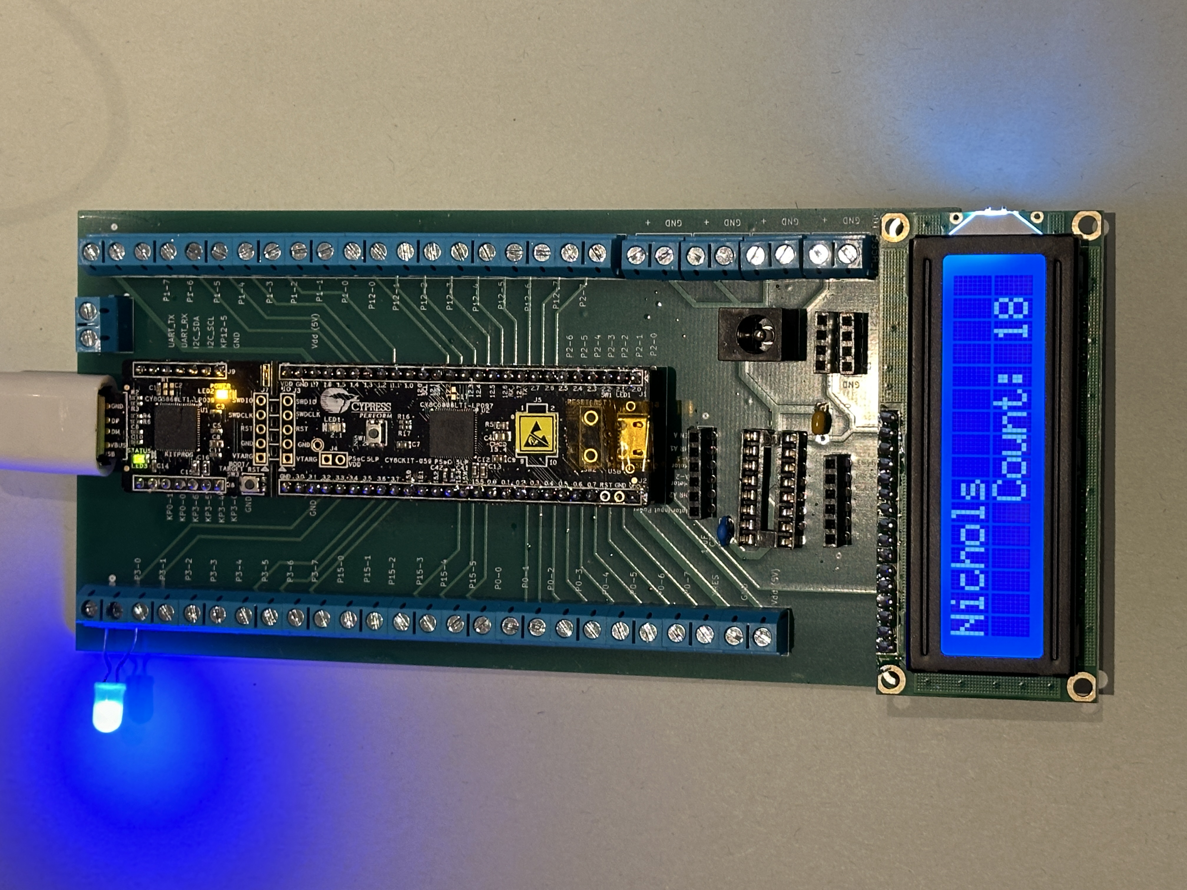
In-class demonstration, using your completed “controller” indicated by writing your name on the back side of the PCB, display your name in the top left corner of the LCD screen and towards the bottom right corner of the LCD screen, you have “Count:” with values counting up by ones.
-
In-class demonstration of the PSoC`s built-in LED blinking.
-
A Canvas submitted of the Lab`s PSoC Creator archived/zipped file for this lab following the requested file naming method.
Warning
To be eligible to receive credit for the code submission, you must receive Demonstration credit.
General Steps for Completion of Lab
Step 1 - Double Check Parts
To Hide Details
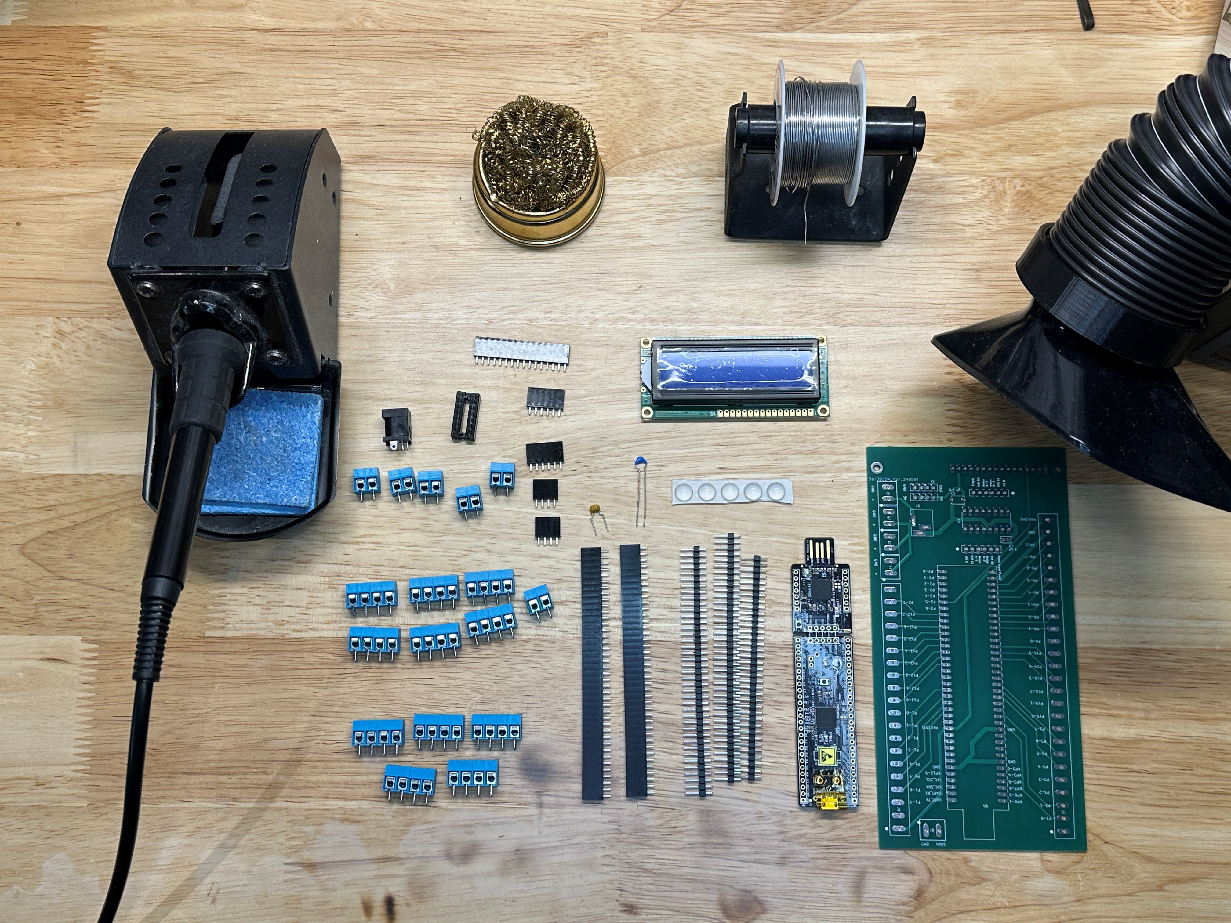
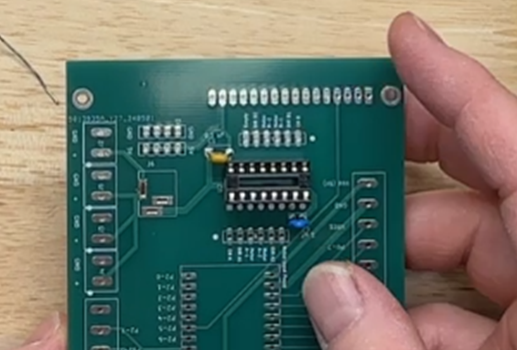
The following table lists the parts, quantities, and PCB designators. Figure 1 shows a view of most of the parts needed to build mock controller for the Robotic Systems courses.
| QTY | Part Name | PCB designator(s) |
|---|---|---|
| 1 | Custom PCB | |
| 2 | 40 pin Female Header | U1 |
| 14 | 4 pole Screw Header | J1 (6.5x), J2(2x), J9 (5x), J8 (0.5x) |
| 1 | DC Power Jack | J6 |
| 1 | 16 pins IC Socket | U2 |
| 2 | 6 pin Female Header | J11, J12 |
| 1 | 0.1 uF Capacitor (104) | C1 |
| 1 | 1 uF Capacitor (105) | C2 |
| 2 | 4 pin Female Header | J7, J10 |
| 1 | 16 pin Female Header | U3 |
| 2.5 | 40 pin Male Header | |
| 1 | PSoC 5LP Development Kit | |
| 1 | Basic 16x2 Character LCD | |
| 1 | USB Cable (1-Feet Type A Male to Female USB 2.0) | |
| 5 | Bumper Pads | ** To provide protection for accidental shorts and/or scratches from PCB |
| 4 | Socket Head Screw M2.5, 14 mm Long | ** Use to attach LCD Screen to PCB if so desired. |
| 6 | M2.5 Nylon Hex Nut | ** Use to attach LCD Screen to PCB if so desired. |
Step 2 - Solder Parts
To Hide Details
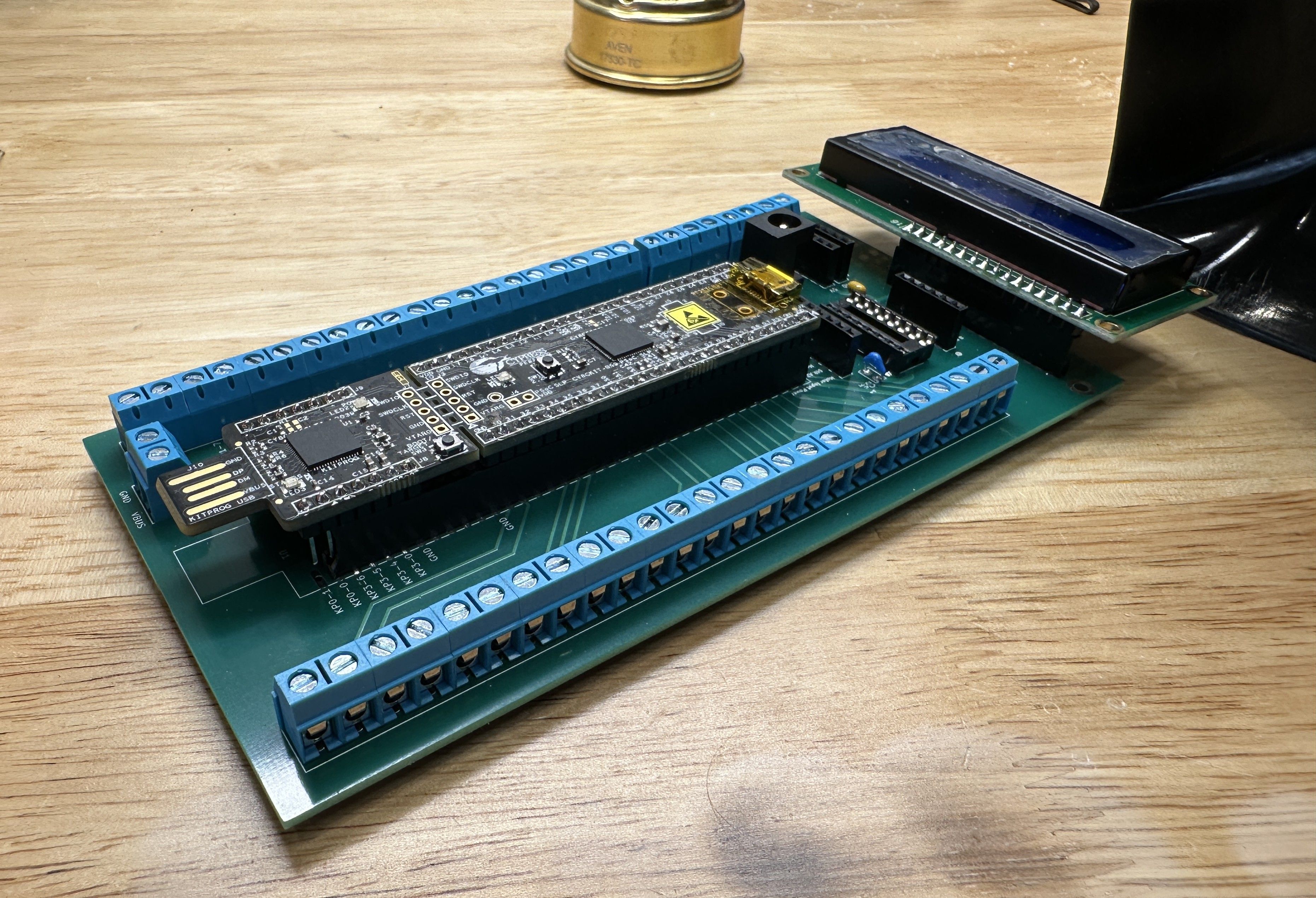
Solder the different parts on to build your “Controller,” similar to what is shown in Figure 2. See below for more details and steps.
TIPS
- When soldering through-hole parts, it is commonly recommended that solder parts be attached in order of smallest height to largest.
- Place/work with parts to help keep the PCB “level” to help keep parts tight to the board.
- Solder one (or two, if needed) to hold the part in place so you can inspect and correct the positioning before soldering all the pins.
- Both the pad and pin need to get hot so that the solder flows and bonds correctly.
- Too much heat for the type of solder can ruin the solder joint(s).
- When part alignment matters, place all the parts and then solder a few pins to hold the alignment. Then, if applicable, separate into a sub-group before finishing the soldering of the remaining pins. Check and be careful not to mess up that alignment.
Using the tip from above, it is recommended that you add parts in the following order:
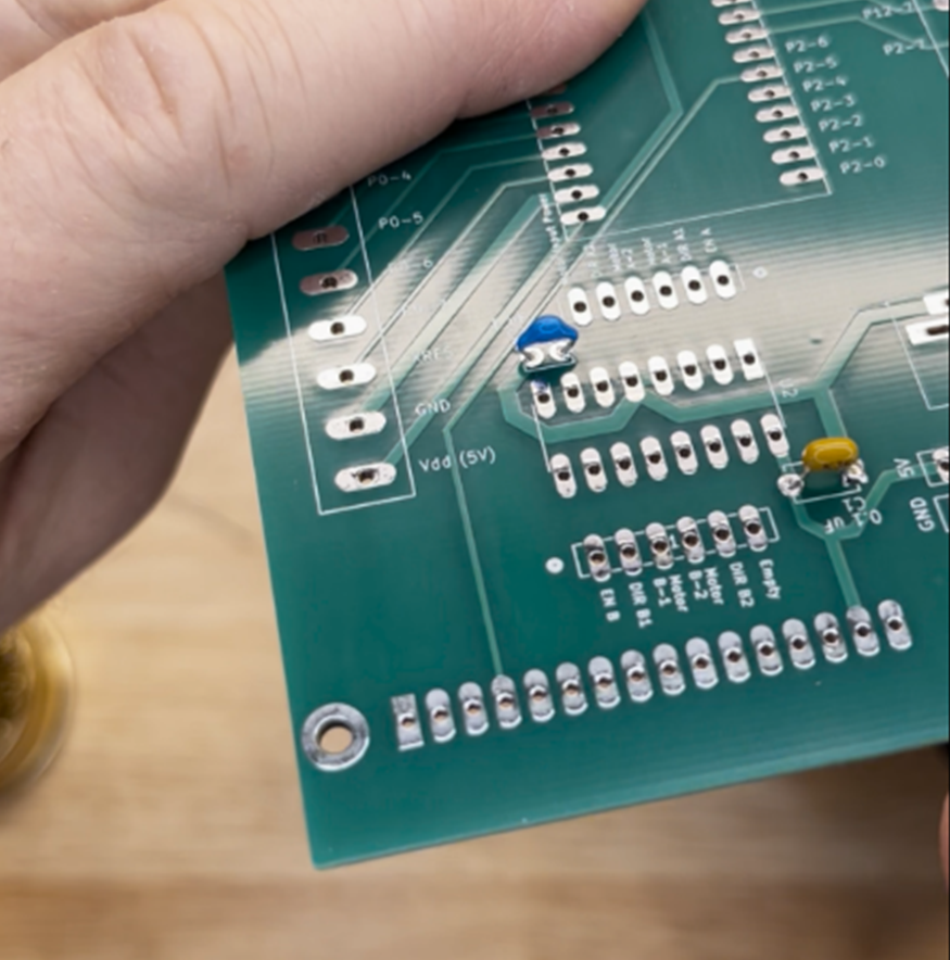
- Capacitors. (Figure 3 for refernce shown farther below)
- Dip socket. (Figure 4)
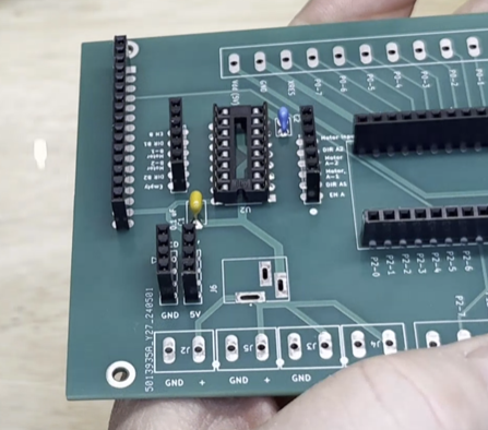
- Make sure the notch on one of the short ends of the DIP socket is next to the U2 marking. This notch indicates how the IC chip get inserted in where both notches are together. This notch is clearer to see in in Figure 6.
- Female and male headers at U1 (PSoC). (Figure 5)
- Remaining female headers at J7, J10, J11, J12, and U2. (Figure 6)
- Screw headers, connected together at J1 and J9.
- Remaining screw headers.
- DC Power Plug.
- Male header to LCD screen.
- Bumpers on the back side of PCB.
Attention!
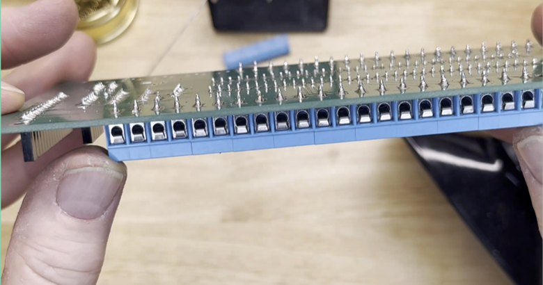
Make sure the opening on the side of the screw terminals are facing out, away from PCB, to make it easy to secure wires later. (Figure 7 for refernce shown farther below)
Step 3 - Inspection of Work
To Hide Details
If you haven`t been doing it already, now is the best time to inspect your work on assembling your “Controller.” Things you are on the lookout for are:
- Missed parts. Look for parts you may have forgotten to either add or fully solder. The only opening that will not have something soldered to it are the non-plated mechanical holes for the screws to mount/secure the LCD screen.
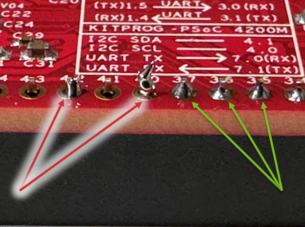
- Quality of soldered joints. Look at all the points you soldered. (a) Do they have the appearance of a slightly melted Hersey kiss? This means that the solder flows in a smooth cone-like shape. See Figure 8 and look at the solder joint the Green arrows are pointing to for reference. Or look at the solder joints back in Figure 7. You do not want balls of solder at the pins like the what the RED arrows are pointing to in Figure 8.
- Check continuity. While inspecting your solder joints, are there places you are not certain they are either (a) making a connection or (b) could be shorting? Now is the time to make sure you will not have problems later.
Step 4 - Understanding Your Controller
Processor
To Hide Details
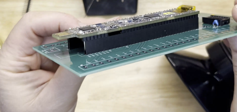
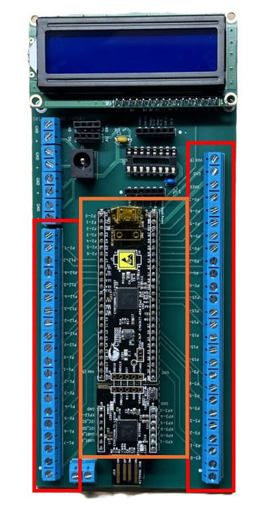
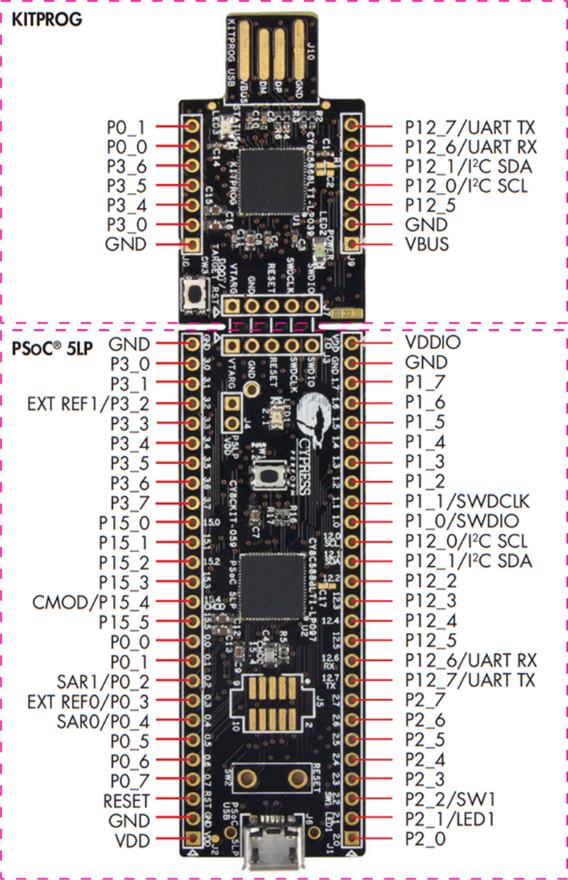
Similar to an Industrial Controller Unit, your mock Robotic System’s Controller has a Processor which is the PSoC 5LP, which is within the Orange center box of Figure 9. To protect our processor, the whole Dev board is supported by header to help prevent the kit’s programmer section from snapping/breaking off from the PSoC 5LP section. Figure 10 shows those two sections and a pin overview of the PSoC 5LP.
Warning!
You can only program this Dev board on the one end with the male USB A through the programmer section of the dev board.
Inputs and Outputs
To Hide Details
Again, like an Industrial Controller Module, the different Input and Output that goes to the processor have a separate connection for easy and secure points of connection. These are in located in the red boxes of Figure 9. The only I/O pins for the PSoC 5LP not on these screw terminal blocks are the ones going to the LCD screen.
Shared Processor Power Levels
To Hide Details
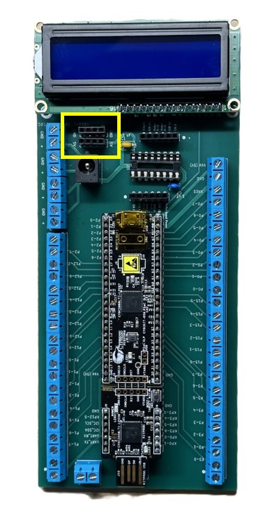
For any of the devices that will be connected to the controller and will be using the same 5 volts, 1/2 an amp power as the PSoC 5LP, there are the two, 5-pin headers indicated by the yellow box in Figure 11 below. In addition to these headers, there are two set of locations within the screw terminal connectors. One set is at the end of screw terminal connectors opposite of the DC power jack and close to the LCD screen. The other set is diagonal to the first noted set, next to the Vbus input power connection.
Note
All power sources have their grounds connected together via a Ground Plane within the PCB board to help you not experience that issue of things not working because the grounds were not tied together. (You’re welcome. I hope because this a lesson you must learn and most ready learn it the hard way.)
Motor Driver Unit
To Hide Details
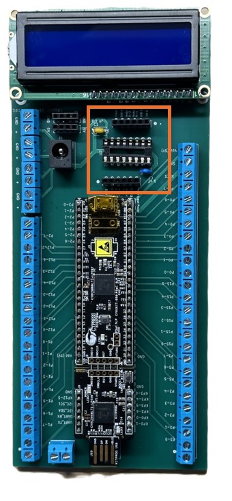
Just like an Industrial Controller, our Robotic System’s Controller processor cannot handle the higher voltage and amperage levels that the motor needs to have to operate without causing damage to the processor. To safely control the motor at a higher level than the processor, the processor communicates with some type of motor controller device. Your kit has been designed to do this with an H-Bridge IC chip. The H-Bridge chip sits in the dip socket and has the needed connections either directly handled with traces within the PCB or to the two headers on either side. We are using a dip socket connection instead of soldering the IC to the PCB for ease of possible repair. These headers and dip socket for our motor driver unit is indicated by the orange box in Figure 12.
Motor Power
To Hide Details
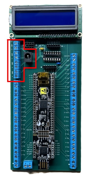
To provide a higher voltage and amperage level for the different motors that will be used in the course, there is the DC power jack along with 4 sets of screw connectors. These have been identified by the red “box” in Figure 13.
User Interface Screen
To Hide Details
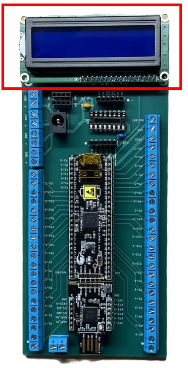
To handle the feedback, one may that a simple indicator light cannot do, a user interface screen is commonly employed. You have been provided with a 2-by-16-character LCD screen that the PCB has the different connection handled for you so that it is a simple process to connect the LCD screen when needed/desired whose location is indicated in Figure 14 by a red box. While you will not be asked to use to in all the upcoming labs, you may find it a useful tool for debugging.
Step 5 - First Code in PSoC
Create a Workspace and Start a Project
To Hide Details
If you have not installed PSoC Creator as part of Lab 0, you will need to go back and do so before moving forward.
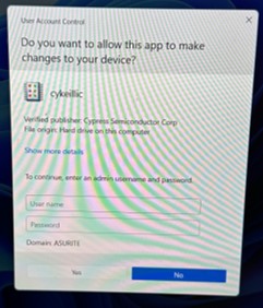
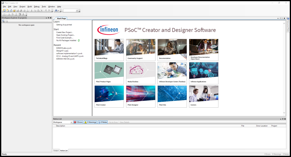
Open PSoC Creator. While opening the program, you might get a pop-up screen that ask to register or allow “cykeilic” app to make changes as shown in Figure 15. You can just say no to this request if you so desire. When the program opens, your screen will look something like Figure 16.
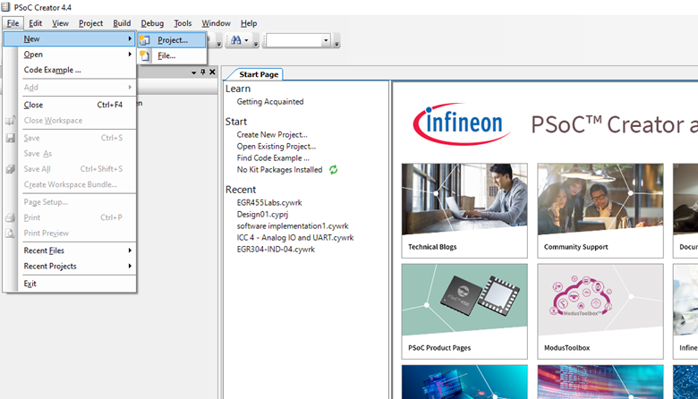
Now to start the process of creating a new project in a new workspace, select File -> New -> Project as show in Figure 17 from the pull-down menu.
The first step in creating a new project will be to choose the type of project to create as shown in Figure 18. Select “Target Device”: PSoC 5LP and “Launch Device Selector.” The “Device Selector” window will open. To narrow the search list, type “CY8C58LP” into the “Series” Filters input. This took my list down to 19 to choose from with “CY8C5888LTQ-LP097” being the last one on the list. Find and select “CY8C5888LTQ-LP097” on your list, then click OK.
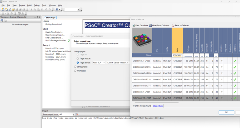
The “Device Selector” window will close so that you are back the previous window of “Select Project Type.” If the filled-in “Target device” is updated to the selection, then select Next.
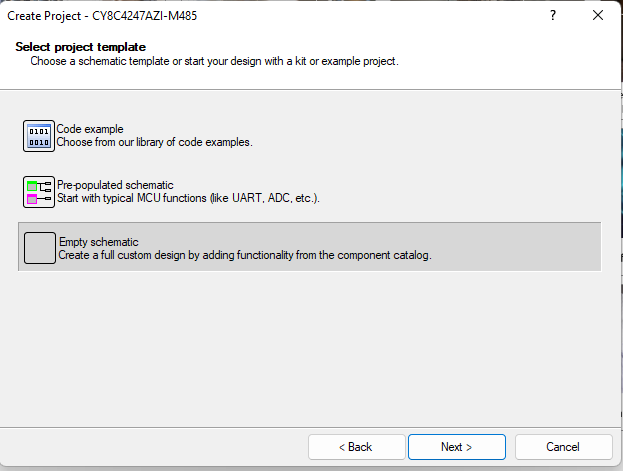
A new window of “Select project template” will open as shown in Figure 19. Select “Empty Schematic” and then Next.
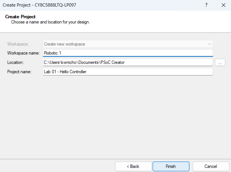
The last step in creating a project is to give it a name, a workspace name, and location to where you want to save the project.
- Workspace is way of grouping several projects together. I will suggest calling it Robotic 1.
- Project is the current/local code group that is within a Workspace. You can open and access all the projects that are within a given Workspace. When you have multiple projects, you will need to select/check which project is active when you go to program the PSoC. (More on that later.)
Note
While it will be shown that all labs for Robotic Systems I in one “Workspaces” folder and Robotic Systems II in another, you can choice how to keep all the project files organized. Having a main Workspace with different projects that have some connection between them is more organized and will allow you to open several project files to view/copy from as reference to the current project. The other option is a new workspace for every new project.
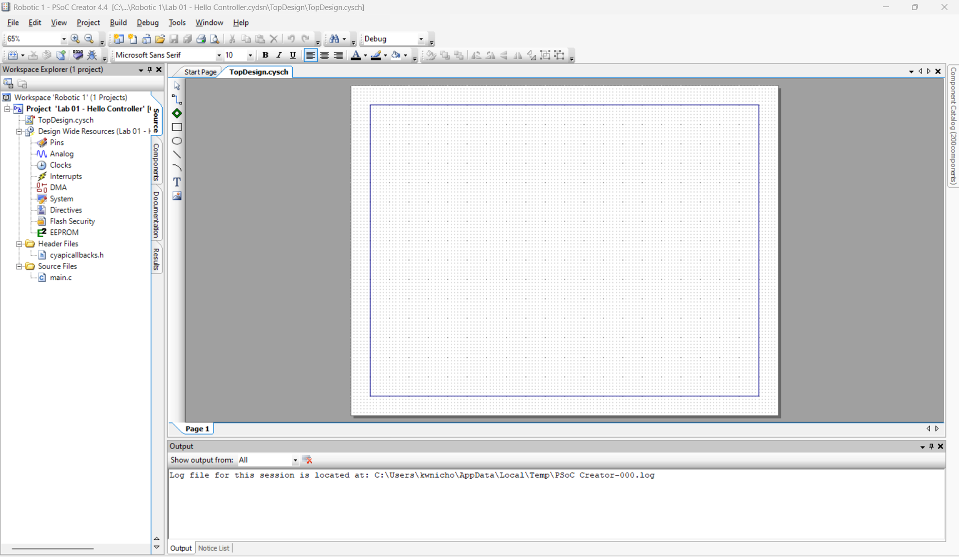
PSoC Creator will then build you a project and when it finishes, your screen will look something like Figure 21.
Connect and Verify Project Setup
To Hide Details
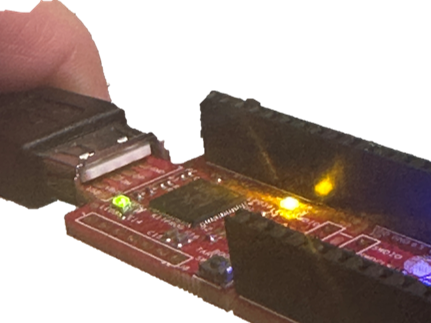
Before going to far, to will be good to check that your first project got setup correctly. To do this, connect the PSoC to the computer you are using with a USB cable. On the PSoC connection side, you need to plug the USB cable onto the PSoC so that the little white spacer is touching the copper pads as shown in Figure 22. When connected, the PSoC will have LEDs on and blinking.
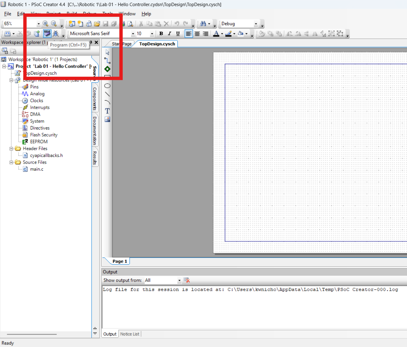
Now let us program the PSoC with this blank project to check if the set-up is correctly so far. To program the PSoC, select the “Program” icon. Figure 23 show what that icon looks like and possibly where it might be located. If everything has been done correctly up to this point, the PSoC 5LP will get programmed without errors and the LED will stop blinking. Additionally, in the “Output” window, it will tell you that it was successfully programmed.
Introduction to PSoC Coding Environment
To Hide Details
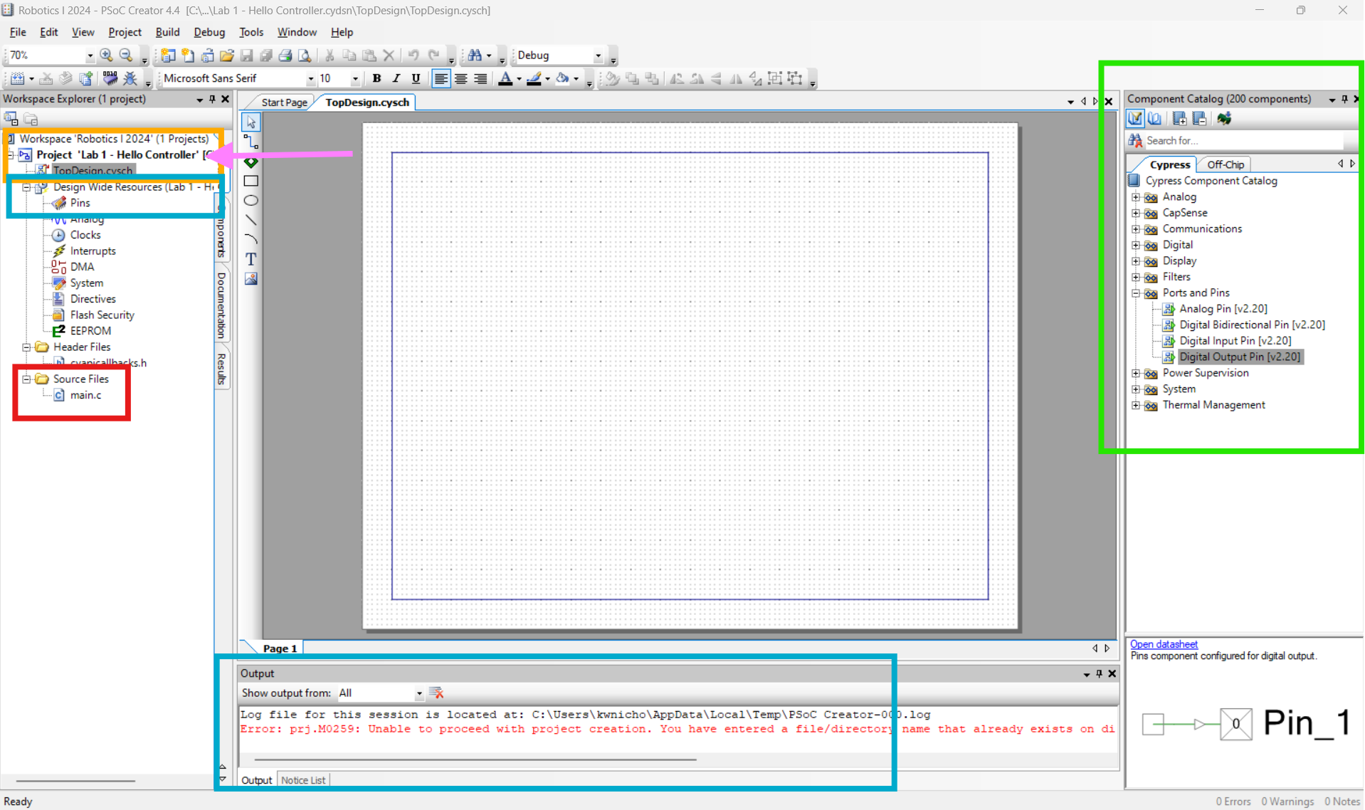
To help you navigate around PSoC Creator, look at the different colored boxes in Figure 24. There are four main areas you will be dealing with within PSoC Creator for the programming the PSoC 5PL in the Robot Systems labs.
- “ TopDesign” - This is where all the component modules will be places and setup acquired to the need. It is generally the tab that opens up when you start a project. If it gets closed, you can reopen it by double clicking on it. You can find it right under the project name as shown by the orange box in Figure 24.
- “ Component Catalog” - The green box in Figure 24 shows where this is located. It is here where you will find all the components modules/blocks are located which you can use in programming. You can search for it by typing in the name or open and look under sections you think it might be located. To use a component module, you select it and then drag it onto the “TopDesign” page.
- “Pins” - The small teal box under the “TopDesign” in Figure 24 shows where one can access the pin allocations. When open, this is where you assign the I/O pins of the modules you placed in the “TopDesign” to the pins of the PSoC chip.
- “main.c” - This is where the ‘C’ code gets written and is show within the red box in Figure 24.
Other things to notice in Figure 24 where the shown “Output” is by default with the large teal box and the BOLD of the project name which the pinkish arrow is pointing to. The bold lettering of the project name indicates it is the current project within the Workspace.
Component Module Setup and Pin Assignment for LED
To Hide Details
As an easy way to get started in PSoC, I want you to first get the blinking LED back as a way of learning some of the basics of PSoC Creator. If you are not currently on the “TopDesign” tab, navigate back to this tab. To get the PSoC to have a digital output that turns something on and off, you will need to add a “Digital Output Pin” to the “TopDesign.” To get to the “Digital Output Pin” module so that you can drag it onto the “TopDesign, in the “Component Catalog” either type “Digital Output Pin” into the search or expand the “Ports and Pins. Select the “Digital Output Pin” and drag it somewhere to be placed on the “TopDesign.”
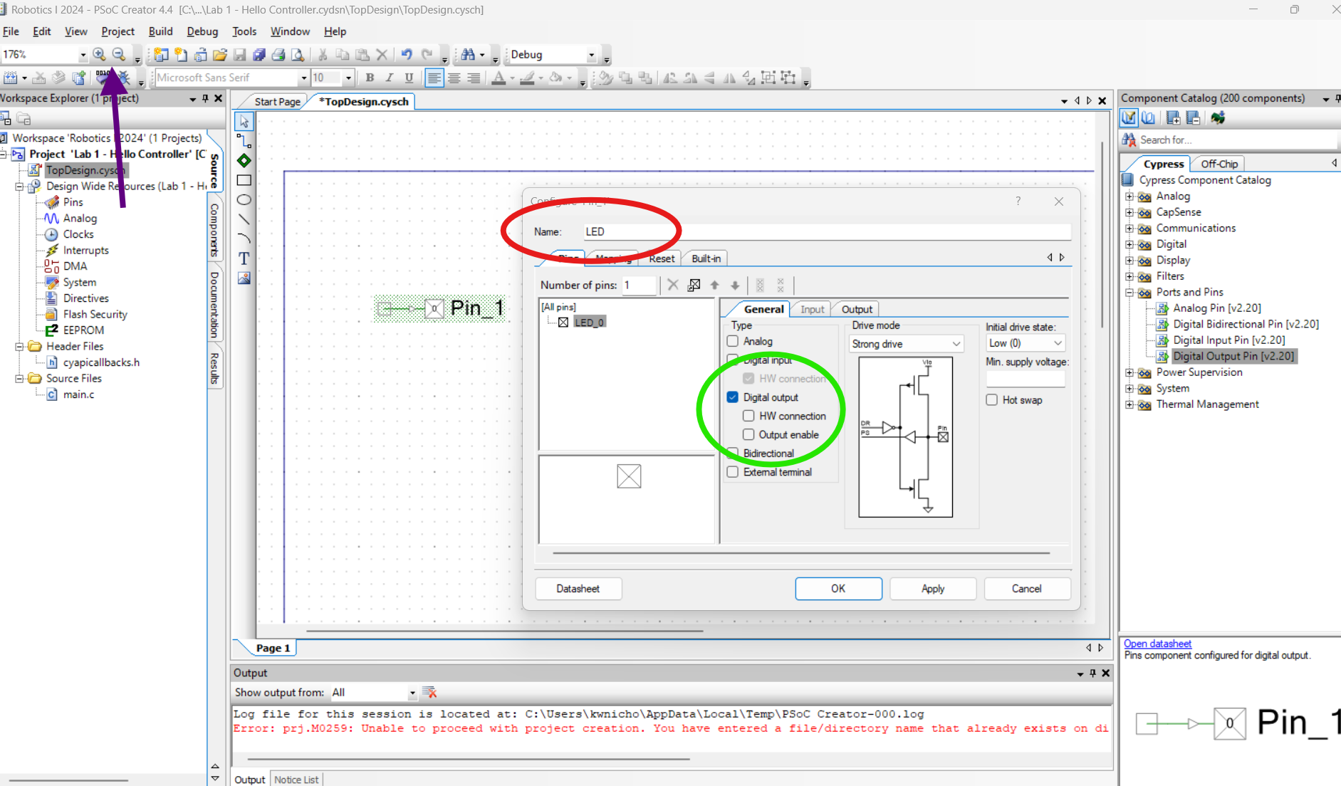
If you want to zoom into the placed modules, you can control the zoom by selecting the “plus” magnify glass that the purple arrow is pointing to in Figure 25.
With the “Digital Output Pin” placed, double click the modules to modify it’s configuration. To have a better understanding of what the pin is within the code, let’s rename it to “LED” as shown in Red circle of Figure 25.
Now, because this pin will be connected to item that is on the PSoC Dev board, uncheck the “HW connection.” After completing those changes, either select “Apply” and then “OK” or you can just select “OK.” When the module configuration window closes, the pin will now have the new name of LED next to it and the side connection pin will be gone.
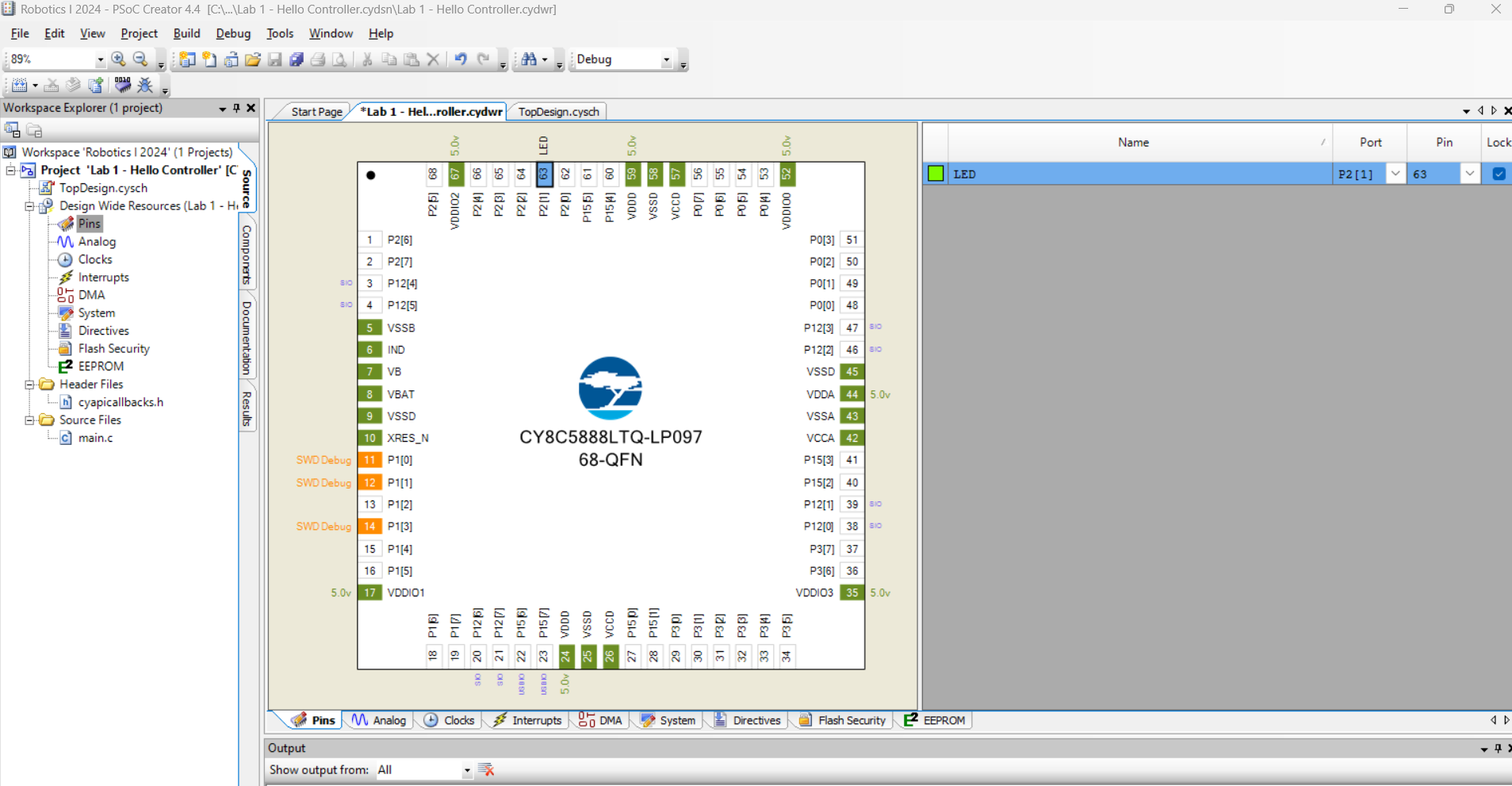
The next step is to assign the digital output module to a PSoC 5LP pin. To do this, open the “Pins” page as shown in Figure 26. This can be done by selecting the Pins on the left under “Design Wide Resources” or if open, the “project name.cydwr” tab. This will open a top view of the microcontroller chip with all its pins. On the right, a list of the pins you have created in this project will be displayed. In this case, you only have the “LED” pin you just created. To assign a “Port”/pin of the PSoC 5LP chip to this component, expand the selection of possible “Ports” and select P2[1]. ” You can confirm which pin that “LED1”, which is the built-in LED, by checking to see what pin number is silkscreened under this LED.
Basic Code to Blink LED Only Three Times
To Hide Details
Note
If you are familiar with “C” programming, you might want to just skim over the following section up pass Figure 29. This section group is meant to start helping and ensure everyone in this class has enough understanding in programming to complete both sections of Robotics. Be aware, as you go through the course, things build up each other with less basic guidance.
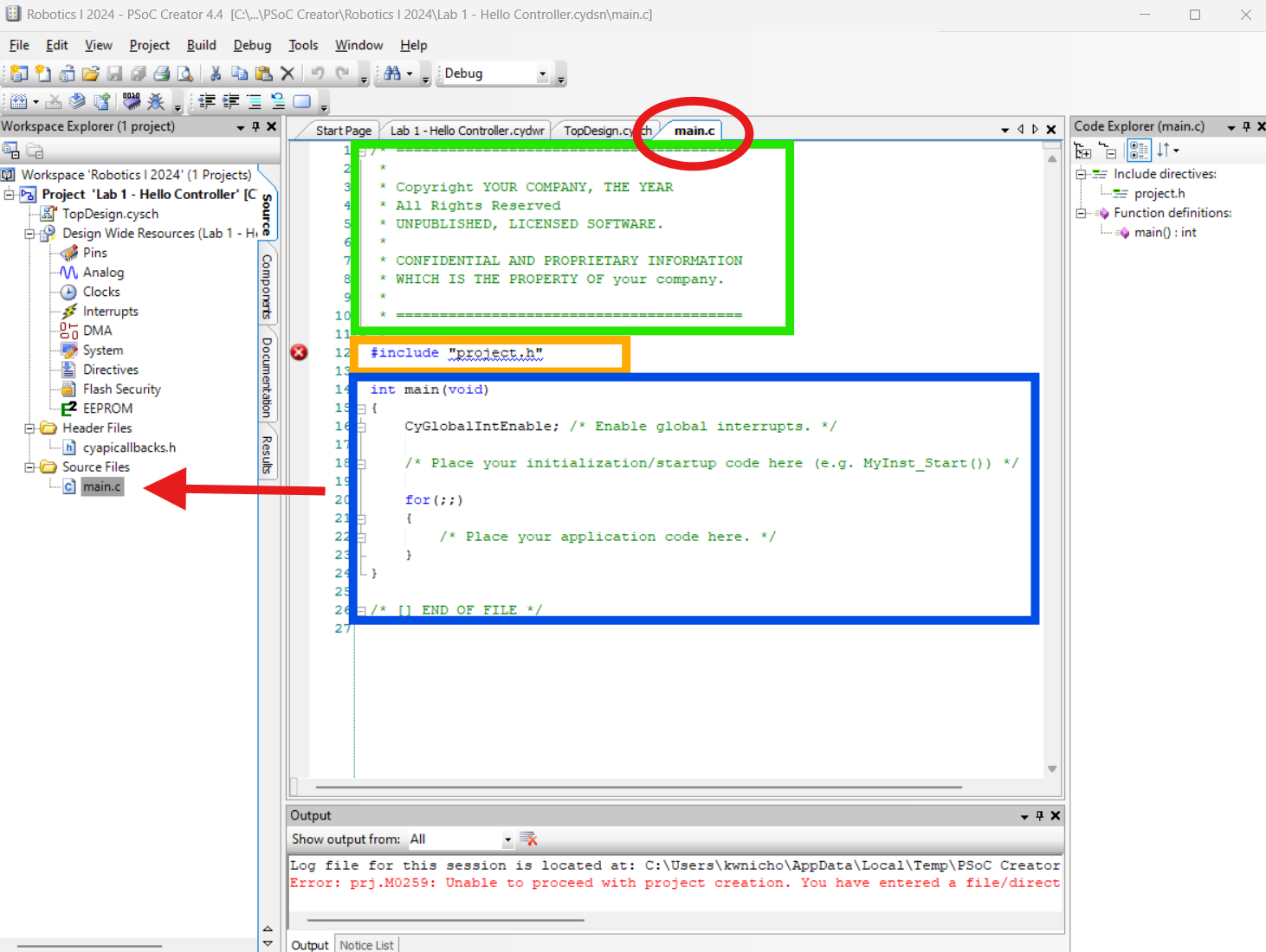
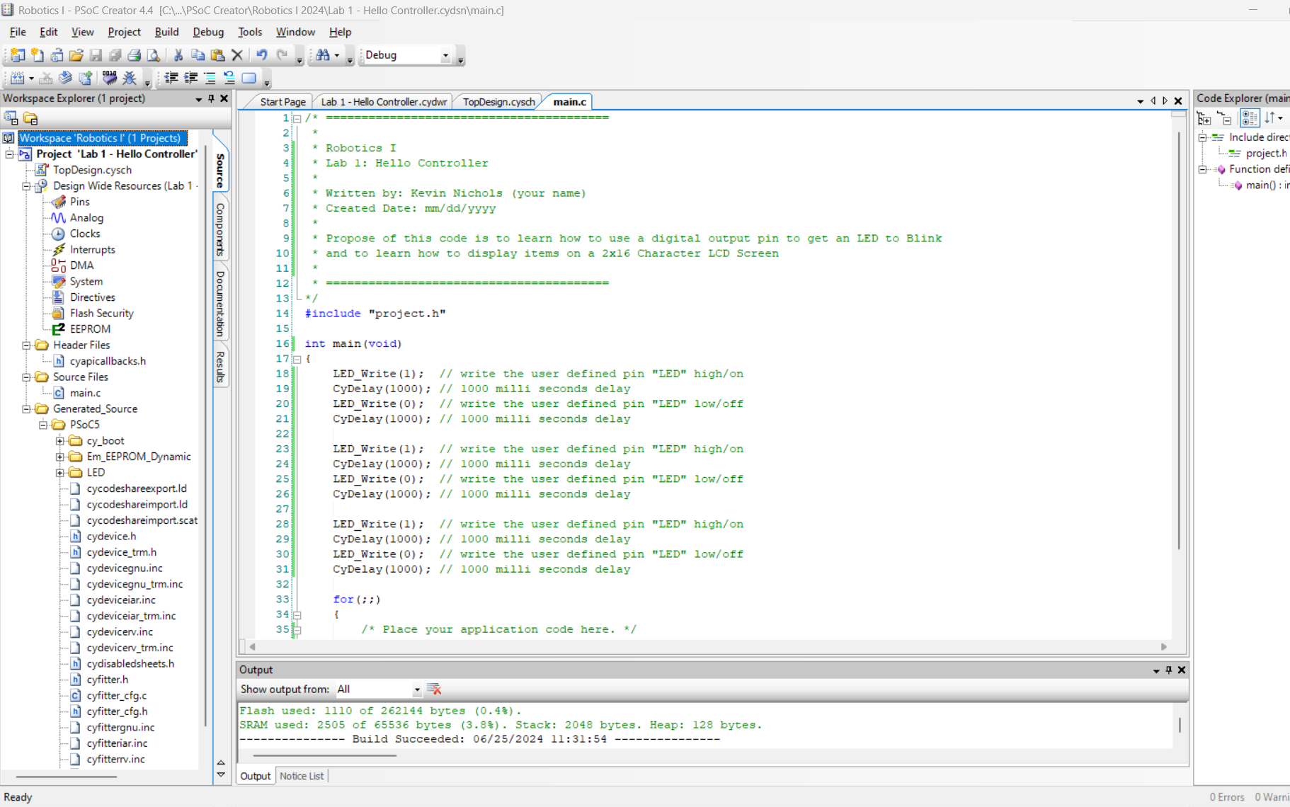
As a means of introduction to ‘C’ code and writing code in PSoC Creator, we will start by first writing code to blink the built-in LED only three and then do nothing only the controller has been reset. After that, you modify the code to blink continues. To write/insert code, you first have to get to the “main.c” file page. You gain access to the “main.c” file page by selecting it from the top tab if it was already open as indicated by the red circle in Figure 27 or opening it by selecting “main.c” under “Source Files” on the left which is where the red arrow is pointing to Figure 27.
On this generic base main file page, the initial code has three main sections which are highlighted by the three colored squares in Figure 27. On the top, within the green square, you will find a generic comment area. You can edit them or delete them off. I will follow a level of coding standards and edit the notes. Depending on the level of coding standards you are following will depend on what information is included in this section. As a bare minimum, most include the name of who initial wrote the code, the date it was created, description of what the code is meant to do. If this was a code that got edited or had a revision to it, I would include the revision date and by who. I will include the Project name since PSoC creator can have multiple “main.c” open and by including the project name in this section will help provide a level of maintainability of organization.
The next section of the code is highlighted by the orange box in Figure 27. This section is where global items to the code are placed. One such global item that is placed here are the “header” files, which is a different way of saying supporting code library, that are needed to support functions within the code.
The last section of code which is within the blue box of Figure 27 is the main body of code. What in within this section is main function part of the code. As the level of code increases, other functions may be included as a way to do repetitive task without having to place the same lines of codes multiple times to accomplish the same thing. Depending on where the lines of code are placed within the main function block will cause different results.
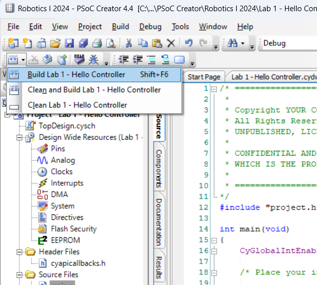
Before going farther, it would be a good time to “Build” the project so that pin variable will be available as the code gets entered into main function of the code. Figure 28 shows where and what the tool icon looks like. Since we have only added one component and have not done lots of editing, you currently do not need to do the “Clean and Build.”
I am going to first start by modifying the initial code comments to the style general style I talks about earlier and can be seen in Figure 29.
Note
For code that gets submitted, it will be expected that one can find at least your name up in this comment section.
The next thing will be to clean up the initial code by deleting the global interrupt and the comment line right after the interrupt.
Now let us get the LED to blink. Right after the main function’s curly bracket, in place of the deleted interrupt, I want you to start typing the name of the pin you named it. In my case it will be “LED”, followed by an underscore “w.” As you type, you will have a list of variables you can select that gets smaller the more you type.
- This can be a way of finding commands you can use with a given variable type.
- This works with all variables after Building the project.
By the time I have typed “LED_w”, I see the “LED_Write” on the list of variable which I then can select to insert into the code. At this point, you will have a red circle with a white ‘X’ to indicate there is an error with that line of code in its current state. After “LED_Write,” the program is expecting a set of parentheses with a value in-between them. To have the “digital output” pin so as to provide a “high” electrical state to turn “on” the LED, the write digital value needed is “1” (which is similar to high). For the code to know that is the end of that line of code, it needs a semicolon at the end. With that, you should notice that the error circle has gone away.
Note
In many programming languages, the Curly brackets are used in sets to enclose the statement group or function. Other names for Curly brackets are braaces or curly braces.
To provide time to see the LED turned on before being turned off, the code needs to have a delay in it. For now, let us use a one second delay. To do this, we delay the code by 1000 milliseconds with the “CyDelay” command with the desired delay time enclosed within a set of parentheses.
After the delay, to get a blink of the LED, we need to turn it off, following the similar steps as to turn on the LED. However, to put the pin in a “low” state, the write digital value is “0”.
Just like when you turn on the LED, we need another delay to be able to see the LED go off. To have a rhythmic pattern, use the same delay time of one second or 1000 milliseconds. If you want to slow down the blinking rate, you would increase the delay time.
Copy and paste these four lines of code two more times to get the LED to blink only on and off three times followed by nothing until the microcontroller is reset/restarted. You code will look similar to the code shown in Figure 29.
Before going on, I want to program the PSoC and observe the results.
What happen? (To repeat, either unplug and re-plug in the UBS cable or press the “Reset” button that in located near the drilled line pattern.)
The LED blinks only three times before stopping was due to where these lines of code are located within the “main.c” file. The main function, will execute only once, just like other functions unless there is looping command like “for” or “while” that holds and causes the code to repeat.
Clarification Note
Yes, we left the “for” loop in the main and truly that was where the code was cycle around unit the PSoC had a reset. However, if you deleted or commented out the “for” loop, you would have the same results.
Before moving on to the LCD screen, let us modify and simplify the code so the LED blinks continuously. Cut and paste one of the three sets code and paste this grouping in a way as to remove the comment that is within the “for” loop. Because the “for” loop looping-condition is blank, the code will repeat this “for” loop unit the PSoC is removed from power or gets reset.
For now, I want you to comment out the other two groups of code that was written earlier. Here are few of the ways to comment lines of code in PSoC.
- Type a double backslash in front of that line of code. This comments out just that line.
- Type a ‘ /* ‘ in front of a section to be commented out and then ‘ */ ‘ at the end of the section.
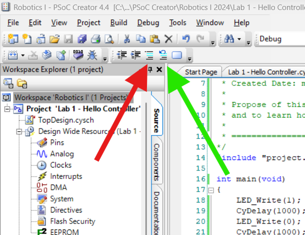
- While on the line or selected group of lines you want to comment out, select the “Comment Section” icon. (Red arrow in Figure 30.)
- Now if you want to Uncomment Section, while on the line or on the selected group of lines you want to remove the comment marks from, select the “Uncomment Section” icon. (Green arrow in Figure 30.)
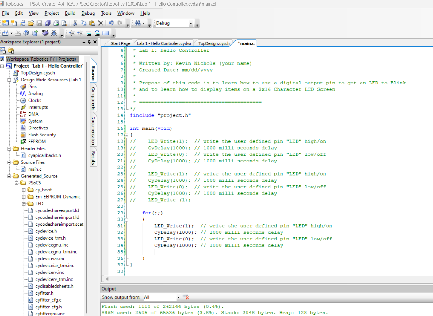
Figure 31 shows the current state of where I am at with this code. Program this version of the code onto the PSoC to verify you now have a blinking LED.
Step 6 - Learning How to Work With the LCD Screen in PSoC Creator
To Hide Details
Imporant Choice
You will need to do one of the follow options for the next part of this lab.
- After demonstrating the blinking LED for credit, comment out all the blinking lines of code and remove the LED pin from the “TopDesign.”
- Start a new project for just the LCD Screen part of the lab leaving the blinking code alone.
- Work with the LED stuff form earlier but be able to explain why the count and LED blinking are not happening at a consist rate.
- Use a personal LED and connect it to a pin other than P2[1] so that it blinks at a consist rate while the LCD screen increaments.
To get the LCD character screen to work, you will need to go through the three similar steps of first adding the component module, then assign pins to the module, and finally add some code.
Component Module Setup
To Hide Details
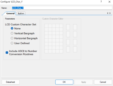
On the “TopDesign” page/tab, add the “Character LCD [v2.20]” component module to the “TopDesign.” The “Character LCD” component module can be found under Display. Figure 32 shows the default settings inside the component module. There is nothing that needs to be changed, added, or selected within the configure of the LCD module.
Assigning LCD Module Pins
To Hide Details
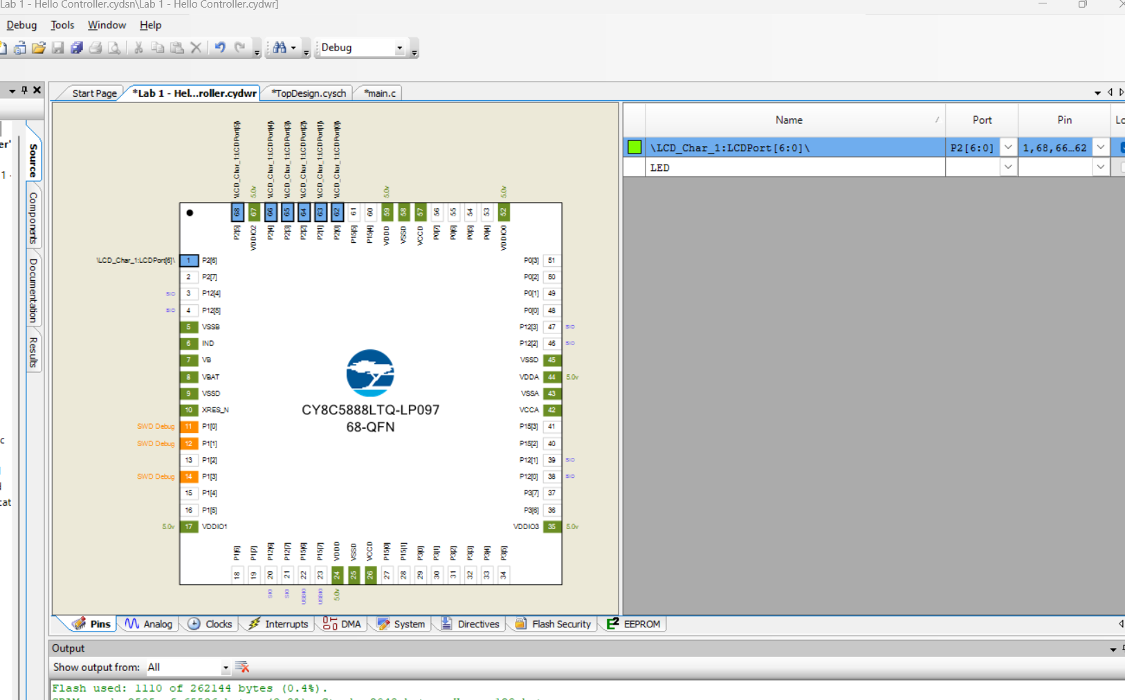
With the component module placed in the “topDesign”, the pins now can be assigned to the LCD module. For the LCD component module, you will select the array of 7 pins which is (P2[6:0]), as shown in Figure 33.
Initial Code of the LCD Screen
To Hide Details
Copy the following example code that will write a message of “Hello Controller” and increment count by ones up to 49. Review the comments to help understand how you make the changes to the display code to get the demonstration credit.
Note: This code still has line of code to possible blink a LED.
/* ========================================
 *
 * Robotics I
 * Lab 1: Hello Controller
 *
 * Written by: Kevin Nichols (your name)
 * Created Date: mm/dd/yyyy
 *
 * The purpose of this code is to learn how to use a digital output pin to get an LED to Blink
 * and to learn how to display items on a 2x16 Character LCD Screen
 *
 * ========================================
*/
#include "project.h"


int main(void)
{
    LCD_Char_1_Start(); //Starts the module and loads custom character set to LCD, if it was defined.
    LCD_Char_1_CLEAR_DISPLAY;
    LCD_Char_1_Position(1,0); //Sets the LCD cursor’s position to the row and column entered
    LCD_Char_1_PrintString("Hello Controller");//Prints a null-terminated string to the screen, character by character.
    LCD_Char_1_Position (0,6); //Sets the LCD cursor’s position to the row and column entered
    LCD_Char_1_PrintString("Count:");

    int i=1; //created a counting interger variable
//    LED_Write(1); // write the user defined pin "LED" high/on
//    CyDelay (1000);

    while (i<50) // while 'i' is less than 50
    {
        LCD_Char_1_CLEAR_DISPLAY;
        LCD_Char_1_Position(0,13); //Sets the LCD cursor’s position to the row and column entered
        LCD_Char_1_PrintNumber(i); //Prints the integer value if "i" of a 16-bit value as left-justified ASCII characters
//        LED_Write(~LED_Read()); //toggle LED state
        CyDelay(1000);
        i=i+1; // increment the count value by 1

    }
}

/* [] END OF FILE */
Step 7 - Test and Modify Code for LCD Screen
To Hide Details
After reading through the comments of the provided LCD basic code, modify the display code in a way so that your Last Name, or at least the first 16 characters of your last name, prints in the top left corner of the LCD screen. Then, approximately in the middle of the second line, print “Count:” followed by the current value of the increasing count value. Figure 34 shows an example of this with an external LED blinking.